Tuesday, 8 July 2025

How a Signal Generator Helps in PCB Repair

 Great question! A signal generator (also known as a function generator) is another very useful tool for electronics repair and testing. While a digital oscilloscope helps you see signals, a signal generator helps you inject known signals into the circuit. This makes fault-finding and performance testing much easier—especially in analog audio, RF, communication, and digital circuits.
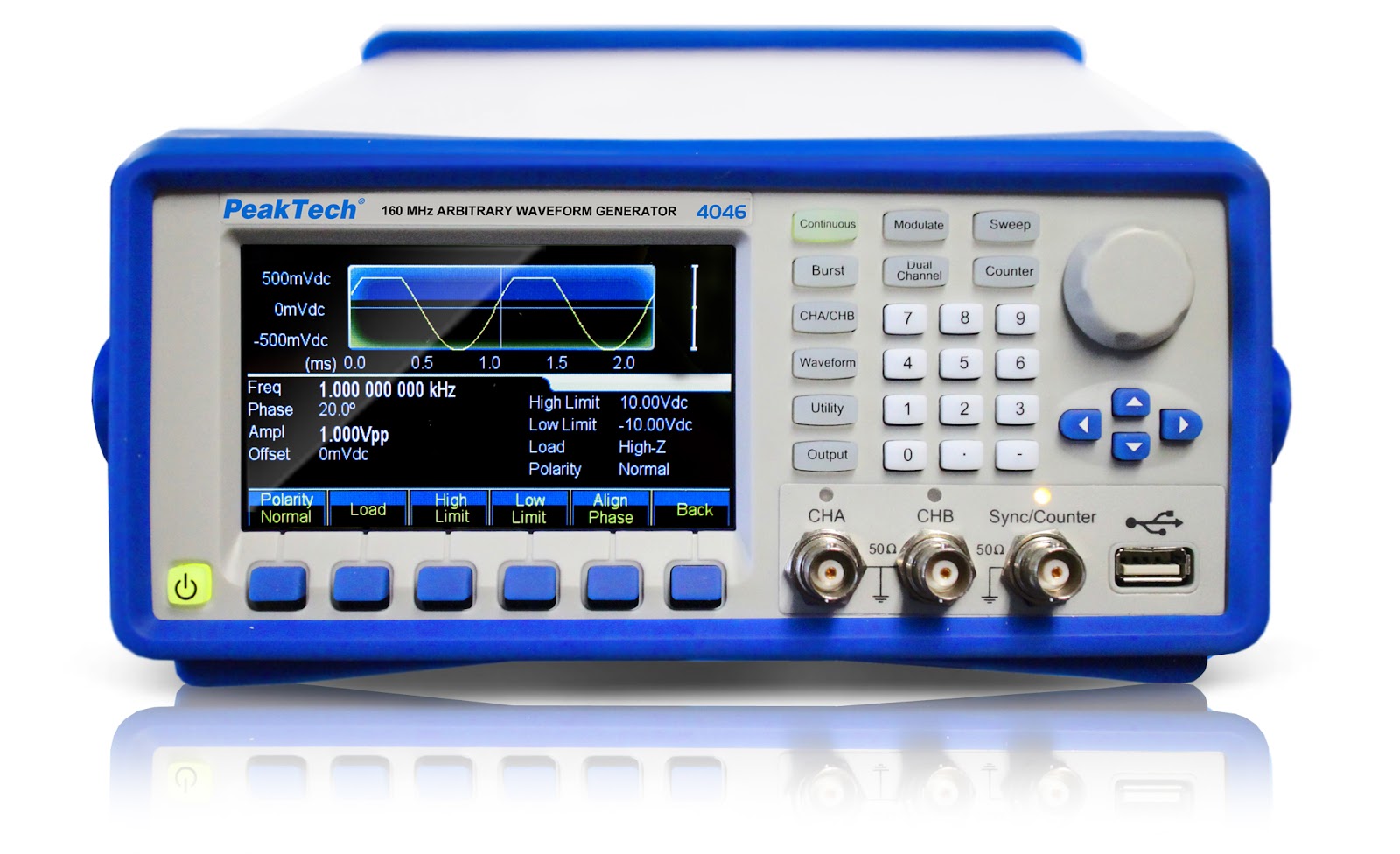


๐Ÿ› ️ How a Signal Generator Helps in PCB Repair

๐Ÿ”น 1. Testing Amplifiers and Audio Circuits

When repairing audio amplifiers or speaker systems:

  • You can inject a 1kHz sine wave into the amplifier input.

  • Observe the output on the oscilloscope.

  • A clean sine output means the amp is working fine; distortion, clipping, or no signal means there’s a problem.

✅ Real Use: I once repaired a PA amplifier by injecting a test tone. The preamp stage was fine, but the power stage wasn’t amplifying. Tracing the signal stage by stage helped isolate the faulty transistor.


๐Ÿ”น 2. Troubleshooting Stages in Signal Path

In communication or processing circuits, you can:

  • Inject square waves or pulse trains.

  • Check how each section processes the signal.

This is useful in:

  • Filter circuits – To test frequency response.

  • Digital logic ICs – To simulate clock or data inputs.

  • Timing circuits (e.g., 555, counters) – To trigger or reset circuits.


๐Ÿ”น 3. Testing Oscilloscope and Probes

You can also use the signal generator:

  • To calibrate or verify that your oscilloscope probe is working correctly.

  • To test bandwidth and distortion measurement setups.


๐Ÿ”น 4. Simulating Missing Signals

In faulty boards, sometimes the microcontroller, clock circuit, or sensor isn't producing signals. A signal generator can simulate those inputs to test whether the next stage works.

✅ Real Use: In one project, a dead IR receiver circuit wasn’t triggering the output stage. I injected a 38kHz modulated signal using the generator and confirmed that the output section worked. So the IR sensor was faulty.


๐Ÿ”น 5. Component Testing

Some passive components (filters, transformers) and even certain ICs can be tested by applying known signals:

  • Use sweep function to test filters.

  • Inject low-frequency signals to check transformer or coupling capacitor behavior.


๐Ÿ“Š Summary Table: Where Signal Generator Helps

ApplicationSignal UsedPurpose
Audio amplifier testingSine wave (1kHz)Check output stages
Digital logicSquare waveSimulate clocks/data
IR/remote circuit38kHz modulatedTest receiver function
Filters/RC circuitsFrequency sweepAnalyze response
Faulty microcontrollerPulseSimulate missing trigger
Signal tracingAny waveformTrack signal path with scope

๐Ÿ”ง Final Words

A signal generator + oscilloscope is a powerful combo. You inject a test signal using the generator and observe the circuit's response using the scope. Together, they help:

  • Reduce guesswork

  • Find open signal paths

  • Verify functionality stage-by-stage

  • Speed up complex repairs

Whether you are working on LED TVs, amplifiers, SMPS, or embedded boards, the signal generator is a must-have tool for serious electronics repair.


Absolutely! A signal generator is very helpful in troubleshooting SMPS (Switched-Mode Power Supply), especially during fault-finding and when the control IC is not producing signals, or when you're checking gate drive, transformer behavior, or startup problems.

Here’s a clear breakdown of how a signal generator helps in SMPS repair:


⚡ How Signal Generator Helps in SMPS Troubleshooting

๐Ÿ”น 1. Simulate PWM Gate Signals

Many SMPS circuits use a PWM IC (like UC3842, TL494, SG3525, etc.) to drive MOSFET gates. If the IC is dead or not producing output, you can:

  • Inject a PWM signal (e.g., 20kHz–100kHz, 5V peak) from the signal generator into the gate of the MOSFET (through a gate resistor).

  • Observe whether the transformer starts switching and output voltage appears.

✅ Real Example: I had a dead SMPS where the PWM IC was faulty. Injecting a 50kHz square wave to the gate proved the power stage was fine. Only the control circuit needed repair.


๐Ÿ”น 2. Testing Transformer Behavior

Injecting a square wave into one winding of a transformer allows you to:

  • Check for proper inductive behavior (waveform on secondary).

  • Identify shorted turns or open windings.

  • Observe waveform ringing or distortion if the transformer is damaged.

Use low voltage (1–5V) and limited current to avoid damage.


๐Ÿ”น 3. Triggering Protection Circuit Debugging

Some SMPS have over-voltage, over-current, or feedback protection. If the SMPS shuts down instantly, you can:

  • Inject a test signal into the feedback or sense line.

  • Confirm whether the protection is falsely triggering.

✅ Example: One supply had a feedback pin stuck high. Injecting a 2V DC + ripple waveform showed that the supply would restart only when FB was normal. Fault traced to an open opto-coupler.


๐Ÿ”น 4. Clock Injection in Synchronous Designs

Some SMPS designs (especially digital ones) use external clock sources. If the clock crystal or oscillator fails:

  • You can inject a square wave clock signal into the IC’s clock input.

  • If SMPS starts working, it confirms clock section is faulty.


๐Ÿ”น 5. Output Ripple Simulation for Post-Regulator Testing

If the output of SMPS feeds another regulator (e.g., LDO), you can:

  • Inject a signal with ripples or noise to the input.

  • Observe how the next stage handles it (ripple rejection, filtering, etc.)


๐Ÿงช Caution When Using Signal Generator on SMPS

Do'sDon'ts
Use low-voltage signals (5V max) when injecting into gates or transformerDon’t inject high voltage directly—can damage components
Always isolate ground between signal generator and live SMPSNever connect signal generator ground to high-voltage circuits directly
Use series resistors (1k–10k) to limit currentAvoid driving directly without limiting circuit

✅ Summary Table

PurposeSignal TypeUse
Test gate drive20–100kHz square waveSee if MOSFET and transformer respond
Test transformer1kHz–10kHz square waveCheck for waveform on secondary
Debug feedbackRamp, DC + rippleSimulate normal feedback signal
Replace missing clockSquare wave (fixed freq)Restart controller temporarily
Verify filteringNoisy sine or burstTest post-regulator behavior

๐Ÿ›  Real World Tip

When debugging a dead SMPS, combine:

  • Signal Generator to inject known signal into gate or feedback,

  • Oscilloscope to monitor output and switching behavior.

This speeds up repair and avoids blind trial-and-error.

Regards
Basavaraj BM

The Role of Digital Oscilloscope in Troubleshooting Electronic PCBs


In the fast-paced world of electronics repair and diagnostics, the digital oscilloscope stands out as one of the most powerful and versatile tools for troubleshooting Printed Circuit Boards (PCBs). Whether you are working on power amplifiers, SMPS, LED TVs, or microcontroller-based circuits, a digital oscilloscope can reveal the “invisible” world of signals and help you identify the root cause of failures with precision and confidence.

Why Oscilloscopes Matter in Electronics Repair

A multimeter can only show voltage, current, and resistance. But electronic circuits operate in dynamic conditions—waveforms, frequencies, pulses, and switching signals. That’s where a digital oscilloscope comes in. It allows you to visualize signal behavior in real-time, helping you catch issues that static tools cannot detect.

Key Roles of a Digital Oscilloscope in Troubleshooting

1. Waveform Analysis

A digital oscilloscope captures and displays voltage vs. time, allowing you to observe:

  • Shape of signals (sine, square, triangle, etc.)

  • Frequency and period

  • Noise, distortion, or unexpected spikes
    These details are essential in diagnosing analog stages in amplifiers, audio equipment, and signal processing circuits.

2. Clock and Data Signal Verification

In digital circuits, checking logic levels is not enough. You need to verify pulse width, timing, rise/fall time, and duty cycle. A scope helps in:

  • Debugging microcontroller clock issues

  • Checking serial communication (UART, I2C, SPI)

  • Ensuring proper timing between digital devices

3. Power Supply Ripple and Noise Diagnosis

A power supply may show 5V on a multimeter, but have hidden high-frequency noise or ripple. Oscilloscopes reveal:

  • Output stability

  • Ripple voltage in SMPS or linear regulators

  • Spikes caused by faulty capacitors or layout issues

4. Component Behavior Observation

With a scope, you can see how components behave under load:

  • Gate signals of MOSFETs in SMPS

  • Switching of transistors in amplifiers

  • PWM duty cycles in motor controllers or LED drivers

5. Short Circuit and Open Line Detection

When no signal appears at a test point, it may indicate:

  • Track cut/open trace

  • Bad solder joints

  • Shorted components pulling the signal down
    Scopes help you follow the signal path to isolate the problem area.


Real-Life Example:

Recently, I repaired an LED TV with intermittent backlight issues. The power board’s PWM controller seemed fine on a multimeter. But the oscilloscope showed that the gate pulse to the MOSFET was irregular. The root cause? A dried-out capacitor affecting the PWM frequency. Without a scope, it would’ve taken much longer to trace.


Choosing the Right Oscilloscope

For general electronics repair:

  • Bandwidth: 50–100 MHz is enough

  • Channels: 2–4 channels

  • Storage: Deep memory helps capture long signals

  • Triggering Options: Helps isolate faults like glitches or delayed pulses

Brands like Rigol, Siglent, Owon, and entry-level Tektronix offer reliable options for repair engineers.


Conclusion

A digital oscilloscope is more than just a fancy screen—it’s your window into the electrical soul of the PCB. It reduces guesswork, saves time, and brings clarity when multimeters and logic probes fall short. Whether you’re a hobbyist, technician, or professional engineer, mastering the oscilloscope is a crucial step toward expert-level troubleshooting.


Here’s an expanded real-life example section showing how digital oscilloscopes helped in actual repair cases. You can use these in your blog or YouTube video scripts:


๐Ÿ”ง Real-Life Examples: How Oscilloscopes Helped Me Solve Tough PCB Problems

1. SMPS Dead – Hidden Low ESR Problem Found

A 12V SMPS was completely dead. Input fuse and primary FET were good. The PWM IC (UC3842) was getting Vcc, but there was no gate pulse.
Using the oscilloscope, I probed the feedback and Vcc pins. The scope showed that the Vcc was pulsing rapidly and resetting—a clear sign of bad capacitor ESR.
๐Ÿ‘‰ Replaced the capacitor near the Vcc pin, and the gate pulses resumed immediately. SMPS came back to life.

2. LED TV – No Display But Backlight ON

Customer complained of "no picture, only sound" on a 32" LED TV. Backlight and voltage rails were present.
Using the oscilloscope, I probed the LVDS output lines from the main board. One or two LVDS lanes were dead flat—no data pulses.
๐Ÿ‘‰ The problem was traced to a faulty BGA chip or dry solder. Reflowing the chip fixed the issue.
Without the scope, I would have guessed T-CON or panel.

3. Ahuja Amplifier – Output Distortion

A 120W PA amplifier was showing humming and distorted output even with a clean input signal. Multimeter showed all voltages were okay.
I connected the oscilloscope to the speaker output and saw a 50Hz ripple riding on the audio waveform. Then I checked the DC rails—there was excessive ripple.
๐Ÿ‘‰ Filter capacitor was weak despite reading full voltage on DMM. After replacing the cap, audio became clean and powerful.

4. Microcontroller-Based Timer – Irregular Output

In an industrial timer board based on an AT89C51 MCU, the relay would not switch reliably.
Probing with a multimeter showed +5V everywhere. But the oscilloscope revealed that the clock crystal was not oscillating properly—signal was unstable.
๐Ÿ‘‰ Replacing the crystal and loading caps solved the issue.


๐Ÿ” Summary: Why These Cases Needed a Scope

ProblemMultimeter ShowsOscilloscope RevealedFinal Fix
SMPS deadVcc OKPulsing/reset VccReplaced bad cap
LED TV no displayRails OKMissing LVDS pulsesReflowed main chip
Amp distortionAll voltages OKRipple on DC lineReplaced filter cap
Timer unstable5V OKClock not stableReplaced crystal

Regards
Basavaraj BM

Do You Really Need a Voltage Stabilizer for SMPS?


Author: Basavaraj B M
Electronics Debug Engineer | 20+ Years Experience | SMPS, PA Amplifiers, and More


Introduction

Many technicians and consumers ask:

“Should I use a voltage stabilizer with a device that already has SMPS?”

This blog clears the confusion around whether SMPS-based equipment like LED TVs, audio amplifiers, routers, or even desktop PCs really need an external voltage stabilizer—and when it's useful, harmful, or unnecessary.


⚡ What is an SMPS?

An SMPS (Switched Mode Power Supply) converts incoming AC voltage to DC using high-frequency switching. Key benefits include:

  • Wide input voltage tolerance (often 90V–270V AC)

  • Compact and efficient

  • In-built protection (overvoltage, undervoltage, short circuit)

Modern electronics (LED TVs, set-top boxes, monitors) already use SMPS, making them more resistant to voltage fluctuations compared to older linear transformer designs.


๐Ÿ”Œ What is a Voltage Stabilizer?

A voltage stabilizer is designed to:

  • Correct high/low voltages

  • Protect devices from brownouts and spikes

  • Deliver steady voltage to the connected load

They were essential when devices used sensitive transformer-based power supplies (e.g., CRT TVs, tape decks).


✅ When You Don't Need a Stabilizer for SMPS

If your device has:

  • A wide input voltage SMPS (90–270V AC)

  • Is rated for Indian grid fluctuation range

  • Has inbuilt surge protection or MOVs

Then an external stabilizer is redundant.

Example:

  • LED TVs, modern PA amplifiers, desktop SMPS: work directly from 170–270V AC.

  • Many modern LED TVs mention “No Stabilizer Needed” on the back panel.


⚠️ When a Stabilizer May Be Useful

You may still consider a stabilizer when:

  • You face frequent power cuts, low voltage (<160V), or high voltage (>280V)

  • You are using expensive audio equipment, sensitive lab instruments, or old SMPS designs

  • Your local supply is unpredictable or noisy

In such cases, a modern digital stabilizer with surge suppression and cut-off feature can protect the input stage of the SMPS.


❌ When a Stabilizer Can Cause Problems

Some stabilizers:

  • React slowly to voltage changes, causing relay click noise

  • Add unnecessary load or heat

  • Create harmonics or waveform distortion (if poorly designed)

Also, connecting a low-cost stabilizer to an SMPS can result in over-regulation or conflicts with inrush current, especially in audio amplifiers or LED TVs.


๐Ÿ”ง Real-Life Case: PA System Repair

A client was using an Ahuja 120W amplifier with a local stabilizer.
Issue: Humming sound and relay clicking.
Diagnosis: The stabilizer’s relay was delaying the AC phase, confusing the internal SMPS and relay of the amplifier.

Solution: Removed the stabilizer. Direct connection improved performance.
Conclusion: Stabilizer was causing more harm than good.


๐Ÿง  Conclusion

SMPS is already a “mini stabilizer” inside your device.

So:

  • For modern equipment in moderate grid conditions, stabilizer = not needed.

  • In rural or extreme grid areas, use a good-quality digital stabilizer with overvoltage and surge protection.

  • Avoid using cheap or old relay-type stabilizers with SMPS loads.


๐Ÿ” Quick Checklist

Device TypeSMPS Inside?Stabilizer Needed?
LED TV (2020+)Yes❌ Not required
Desktop PCYes❌ Unless power is bad
Ahuja AmplifierYes (partial)⚠️ Only if unstable grid
CCTV DVRYes❌ Usually not required
Washing MachineNo/Partial✅ Use stabilizer

๐Ÿ’ฌ Final Note

If you’re unsure whether your setup needs a stabilizer, feel free to comment below or message me. I'm always ready to help fellow technicians and electronics users with practical, tested advice.


Regards

Basavaraj BM


How I Repaired Humming Sound in Ahuja 120 Watts Power Amplifier


Author: Basavaraj B M
Electronics Debug Engineer | 20+ Years Experience | Passion for Repair & Training


Introduction

Power amplifiers are the heart of any sound system, and when they develop issues like humming or buzzing, it can ruin the audio experience. Recently, I received an Ahuja 120 Watts PA amplifier with a continuous low-frequency hum—even when no input was connected. This post shares how I diagnosed and repaired the issue step-by-step.


Symptoms Noticed

  • Constant 50Hz humming sound from speakers.

  • Humming was present without any input signal.

  • Volume control had no effect on the hum.

  • The audio signal path otherwise seemed functional.


Tools Used

  • Digital Multimeter (Fluke 17B+)

  • Soldering station

  • Oscilloscope (for signal tracking)

  • ESR meter

  • Desoldering pump and wick

  • Spare capacitors, grounding wire, star washers


Step-by-Step Repair Process

1. Visual Inspection

The first step was to inspect the PCB and wiring:

  • Found dust accumulation and slight corrosion around ground points.

  • Noticed the power transformer was close to the input stage—a possible source of magnetic interference.

  • The main filter capacitors looked aged but not bulged.


2. Grounding Check

Using the multimeter, I verified:

  • Chassis and signal ground were not bonded properly.

  • Ahuja amps are sometimes susceptible to ground loop hum.

Fix:
I removed the ground loop by:

  • Cleaning all chassis contact points.

  • Adding star washers to the grounding screw for better contact.

  • Tightly securing all ground wires to a single grounding point (star grounding method).


3. Power Supply Filter Capacitors

The next check was the electrolytic filter capacitors (10,000ยตF/50V):

  • Used an ESR meter and found ESR higher than normal (>1ฮฉ).

  • These caps were not filtering the 50Hz ripple effectively, leading to hum.

Fix:

  • Replaced both filter capacitors with new low-ESR 10,000ยตF/63V caps.

  • Soldered with care to maintain polarity and track integrity.


4. Preamp Section Decoupling

Checked the decoupling capacitors (47ยตF to 220ยตF) in the preamp and tone control sections:

  • A couple of caps had minor leakage and degraded ESR.

  • Especially the one at the op-amp power rail.

Fix:

  • Replaced aged decoupling caps with fresh Panasonic low-ESR types.

  • This stabilized the DC rail feeding the preamp op-amp (4558).


5. Signal Path Isolation

I disconnected the input and directly injected a clean sine wave at the power amp input.

  • The hum disappeared, confirming the issue was before the power stage.

Also noticed that the RCA input jacks were loosely grounded, which can cause hum pickup.

Fix:

  • Re-soldered input jack ground to the chassis.

  • Used shielded wire for the input path from jack to board.


Final Result

After all these fixes:

  • Humming completely gone

  • Clear and noise-free audio output

  • Amplifier passed full-load test with 120W output at 4 ohms


Conclusion

Humming in amplifiers is often due to bad grounding or faulty capacitors. In this Ahuja 120W PA amp, replacing old filter and decoupling caps, and ensuring proper chassis grounding, eliminated the hum. Always remember to isolate the stage causing the problem and approach logically—don’t just replace parts blindly.

If you're facing a similar issue in your amplifier, try these steps. Feel free to comment or reach out if you need help!

How I Repaired Dead and Flickering LED TVs Due to Low ESR Capacitors

 Dear friends,

As a service engineer with over 20 years of experience, I’ve seen many tricky faults in LED TVs. One of the most overlooked issues is capacitors with high ESR (Equivalent Series Resistance). Even if they look fine, they can silently kill the power supply or cause display issues.

Here are two real case studies from my recent repairs where low ESR capacitor failure was the root cause.


๐Ÿ› ️ Case Study 1: Samsung 32" LED TV – Completely Dead

  • Model: Samsung UA32FH4003

  • Issue: No standby light, no power, totally dead

  • Initial Check: Fuse OK, input voltage present

  • Clue: No output voltage on power board (5V/12V missing)

๐Ÿ” Diagnosis:

I suspected the secondary side filter capacitors. With an ESR meter, I tested a 470ยตF/25V capacitor. Although it looked perfect physically, it had an ESR value of 5ฮฉ, which is very high (normal < 0.2ฮฉ).

๐Ÿ”ง Repair:

Replaced the faulty cap with a 105°C low ESR capacitor.

✅ Result: 5V and 12V restored, TV powered ON, backlight came up, display normal.


๐Ÿ› ️ Case Study 2: LG 43" LED TV – Flickering Backlight & Auto Shutdown

  • Model: LG 43LF540A

  • Issue: TV starts with LG logo, backlight flickers, then shuts off

  • Backlight & Mainboard: Working

  • Suspect Area: LED driver power section

๐Ÿ” Diagnosis:

Checked filter capacitor in the LED power line – found 220ยตF/35V capacitor showing ESR of 3ฮฉ. This causes unstable voltage, leading to flickering and shutdown.

๐Ÿ”ง Repair:

Replaced with a Panasonic low ESR capacitor.

✅ Result: Backlight stable, no shutdown, display OK.


๐Ÿง  What We Learn from These Repairs:

  • High ESR = Low Efficiency. Even if a capacitor shows correct ยตF value, high ESR can cause ripple, shutdowns, or no output.

  • Always check ESR when TV is dead or shows display issues.

  • Use branded, low-ESR capacitors rated for 105°C, especially in SMPS and LED driver sections.


๐Ÿ’ก Tip for Technicians:

If the board fuse is fine and there’s no output, don’t just check for bulging caps. Use an ESR meter and check every output filter capacitor. One faulty cap can shut down the whole board.


If you're a technician or electronics enthusiast, never underestimate ESR – it can be the silent killer behind many LED TV issues.


Regards

Basavaraj BM

Understanding LVDS and T-Con Issues in LED TVs — A Repair Technician’s Guide

 ๐Ÿ”ง Understanding LVDS and T-Con Issues in LED TVs — A Repair Technician’s Guide

Modern LED TVs use a combination of high-speed digital interfaces to drive their high-resolution displays. One of the most critical signal paths in the TV is the LVDS (Low-Voltage Differential Signaling) link between the Main Board and the T-Con Board (Timing Controller). When there’s no display or abnormal image issues like vertical lines, faded screens, or ghost images, these two sections are often to blame.

In this blog, I’ll walk you through how LVDS and T-Con issues cause common LED TV problems and how I diagnose and repair them in the workshop.


๐Ÿง  What is LVDS?

LVDS is a digital signal transmission system used to send video data from the main board to the T-Con board. It operates using differential pairs at high speed (hundreds of Mbps per lane), allowing accurate transmission of image data with minimal noise.

  • Location: Between the main board and the T-Con board

  • Signal: Differential signals for Red, Green, Blue data, and clock

  • Wires: Typically 10–30 thin wires in a flat ribbon cable


๐Ÿงฉ What is a T-Con Board?

The T-Con (Timing Controller) board is the brain that controls how the pixels light up on the LED panel.

  • Input: LVDS signals from the main board

  • Output: Gate and source signals to the actual LCD panel via COF (Chip on Film) bonded cables

  • Main job: Synchronize signals, refresh the panel, and manage resolution timing


๐Ÿ” Common Symptoms of LVDS/T-Con Issues

Here are some real-world cases I’ve encountered and fixed:

1. No Display But Backlight ON

  • LVDS may be disconnected or damaged.

  • T-Con might be dead or not getting power.

  • Fuse on T-Con (usually marked F1) may be open.

2. White Screen Only (No Image)

  • No signal from main board to T-Con.

  • T-Con working, but LVDS data missing or corrupted.

3. Lines on Screen / Half Display

  • COF IC or ribbon cable issue

  • LVDS cable loosely connected

  • Gate driver problem on the panel

4. Flickering or Ghosting Image

  • Poor LVDS grounding

  • Electrolytic capacitors on T-Con drying out

  • Aging or overheating T-Con IC


๐Ÿ› ️ Step-by-Step Troubleshooting Tips

✅ Step 1: Check Power to T-Con

  • Most T-Cons use 12V or 5V, coming from the main board.

  • Use multimeter to confirm voltage across fuse (F1).

✅ Step 2: Inspect LVDS Cable

  • Reseat the cable on both ends.

  • Look for broken or corroded pins.

  • Use continuity test if needed.

✅ Step 3: T-Con Board Test

  • Touch the main IC — if cold or extremely hot, IC may be dead.

  • Use oscilloscope to probe LVDS pairs for activity (optional).

  • Swap T-Con board (if available) to confirm.

✅ Step 4: Panel Side (Advanced)

  • If T-Con output is OK, but display is still faulty, suspect:

    • COF ICs on the panel edges

    • TAB bonding issues (common in older panels)

    • Source/gate driver failures


⚠️ Important Notes

  • Never power the TV with T-Con or LVDS cable disconnected — it can damage the main board or panel.

  • Some TVs share backlight control through the LVDS cable — if display is dead, check signal pinouts carefully.


✅ Real Case Example

๐Ÿ”ง Repaired a Sony 40" LED TV with white screen issue.

  • T-Con getting 12V

  • LVDS cable tested OK

  • Found shorted ceramic capacitor near T-Con IC

  • Replaced cap → image restored instantly!


๐Ÿงฐ Tools I Recommend

  • Multimeter with diode/continuity mode

  • Magnifying lamp or microscope for SMD inspection

  • Hot air rework station (for SMD components)

  • ESR meter (to check caps)

  • Oscilloscope (optional but powerful for LVDS diagnosis)


๐Ÿ“Œ Final Thoughts

LVDS and T-Con issues are among the top causes of "display but no picture" problems in LED TVs. With proper tools and knowledge, many of these problems can be repaired without replacing the whole panel or TV.

If you're a technician, always keep spare T-Con boards, LVDS cables, and be patient with signal tracing. These repairs not only save customers money but also reduce e-waste in the electronics industry.

Dead SMPS Repaired: Low ESR Capacitor Was the Culprit


๐Ÿ› ️ Dead SMPS Repaired: Low ESR Capacitor Was the Culprit

Switched-Mode Power Supplies (SMPS) are commonly found in a wide range of electronic equipment due to their efficiency and compact design. Recently, I repaired a dead SMPS unit that showed no output and zero power-on indication. This article explains the fault diagnosis process, how I identified the root cause — a capacitor with low ESR (Equivalent Series Resistance) — and how replacing it brought the unit back to life.


๐Ÿ” Symptom: Dead SMPS

The power supply came from a set-top box, rated for 12V, 2A output. When connected to AC mains, there was:

  • No DC output

  • No voltage at the output capacitors

  • No switching noise or pulse at the MOSFET

  • Primary side appeared dead


๐Ÿงฐ Tools Used

  • Digital Multimeter (DMM)

  • ESR Meter

  • Capacitance Meter

  • Oscilloscope (for final verification)

  • Soldering Iron and hot air rework station


๐Ÿงช Step-by-Step Diagnosis

1. Visual Inspection

The board looked clean — no burnt components, no bulged capacitors. Fuse was intact, and NTC thermistor was in good condition.

2. Primary Side Testing

I checked:

  • Bridge rectifier — OK

  • Bulk capacitor (400V) — Charged properly to 310V DC

  • Startup resistor — Within range

  • Power IC (PWM controller) — Had supply voltage, but no output

This pointed to either:

  • A faulty PWM controller (unlikely, as voltage was stable)

  • Or a feedback loop issue

3. Checking the Output Side

I measured ESR of the secondary side capacitors using an ESR meter. One 1000ยตF / 16V capacitor near the output diode showed very low ESR (<0.01 ohms), and almost no capacitance.

⚠️ Note: This is unusual — low ESR is normally good, but in this case, it was abnormally low due to an internal short inside the capacitor, causing it to behave like a low-value resistor.

4. Replacing the Faulty Capacitor

I replaced the suspect capacitor with a new 1000ยตF/25V low-ESR type, rated at 105°C. The old capacitor, when tested out of circuit, showed only 12ยตF instead of 1000ยตF.


✅ Power-On Test

After replacing the capacitor:

  • The SMPS started switching

  • Output voltage stabilized at 12.1V

  • Ripple was within safe limits

  • Load test passed with a 1A and 2A dummy load


๐Ÿ“Œ Conclusion

In SMPS repair, electrolytic capacitors with abnormal ESR values can silently kill the circuit. Most people associate high ESR with faulty capacitors, but this case proves that very low ESR — especially due to internal shorting — is equally dangerous.

๐Ÿ”ง Takeaways:

  • Always check ESR and capacitance

  • Don't rely only on visual condition

  • Use an ESR meter — it's a vital tool in modern power electronics repair

  • Replace secondary caps with good-quality, low-ESR, high-temperature rated capacitors


After a long time i am Presenting one of my interesting story How i repaired an expensive Cable Receiver which is  being supporting in my local cable network for TV Channels.
Since i am an electronic professional i will be having  Regular touch with local electricians, Cable operators, Videographers  ets. Because they are all my regular Costumers.


These kind of receivers are high  critical and cable operator cannot keep extra standby because of its cost  high expensive .Every local cable network area depends only on this equipment which receives low db signals and then amplified, distributed to Users. If such kind of critical equipment's breakdown then the cable operator is in big trouble. His mobile phone will engage in messed of incoming calls and he is not able to serve the costumer. The only solution to him is to get repaired within low time.
One of  my cable costumer faced above situation and he came to me with tension and requested me to get repaired within low time. Every one who do the repair work knows they cannot repair all the different equipment's, Only specialist can do that within the time because they are well experienced, trained and equipped with proper instruments.
For me its really new thing and for the first time i am opening this expensive RF equipment and very querisity to see the inside design. I am very lucky in this  because i have seen many new things, New design ,new technology in my work shop which i have not seen so for at that time .Really this activity is nothing but technology booster to me.
Come let us start the story how i operated and solved this expensive equipment. When i received this equipment as a symptom its temporarily ON for few second and goes to dead. Removed the mains chord and re-Inserted resulted the same symptoms and the cycle repeated. Suspected on SMPS working Issue.
Generally maximum SMPS  are designed multiple DC OUT depending  on the requirement. In this device i noticed +24V,+5V and -5v DC With common ground.
As a thumb rule if  SMPS stops working First we need to check cold test with the help of Multimeter to the Components handle high stress area like Power transistor/mosfet/IGBT/Top switch etc. Hear in this Receiver its purely STR Power supply design. I check the STR For shorts thank god its OK, Checked the PWM IC For shorts ok, Checked the DC Run cat no shorts ok, start up circuit resistors found ok.Now my next step is to check secondery side for shorts ,Step by step checked the secondery diode for the shorts found ok,Feed back voltage divider ckt ok ,Replaced the opto Isolator  IC817
no result .When every thing ok then why this cycling turn ON/OFF ???.
Really its very headach to me.I did not understood the fault route cause.Ultimatly i replaced all the electrolitic secondary capacitor and the equipment regained the life.