Tuesday 17 May 2016

A computer switched mode power supply.


PC SMPS REPAIRED
Hi friends once again welcome to the wonder full world of electronics repair articel.Now i am going to reveal how i repaired A computer switched mode power supply.
I think everyone know what is SMPS & its application.
I don’t want to pull you to the brief theory of power electronics.
Just i am reminding you its operation & applications, let's begin
One of my repair friend brought this high wattage SMPS for repair.


The unit is completely dead there is no any fan movement at all, I opened the chassis & visually inspection made. Now all the necessary testing including input fuse & bridge at primary side of smps components found ok
To become smps repair expert one should have brief knowledge on comparator ic , pwm ic,terms like vref,feed back,CT,RT etc.What are all this term i think new comers may 
 confuse but i hope professional technicians may understand what are all I am talking.


The entire working principle of smps i cannot cover in this article because i am dealing only the problem & its root cause for the above equipment. 
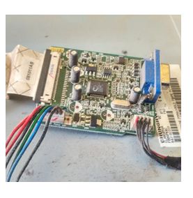
look inside view of smps.


By looking at inner view it is messed with wire bunches .The place for rework is so congested & even no places for proper ventilation. Looking at the inner views I don't know why the SMPS designer has designed like this. The first clue what i got is because of no proper ventilation possibility of electrolyte capacitors failure is more. So in my mind I hoped I can fix this easily & opened my capacitor police ESR meter to check all the secondary filter capacitors. After testing I got 5Volts main filter capacitor 470mfd/16Volts shows wrong reading. I felt very happy to see this suddenly I replaced this and re-powered to see the result.
After re-check there is no good result .Fan has moved for two seconds & tripping off  & no 5volts. I was not happy to see this. I searched an internet to see the circuits for further analysis. Go through the circuit below.


Since it seems to be critical one must have proper schematics to resolve the issues.(Note: Above circuit is Typical circuit choose to make you understand)
After deep looking in to the circuit LM393 is the main circuits which is making to trip off. Sure I will explain what is  happening here for tripping off. Before one should know  the data sheets for both comparator ic LM339 & PWM IC TL494.  


TL494


 Please concentrate at pin # 5 of LM339 in above circuit.Because of R33 4.7 K ohms Out of tolerance when smps is ON at no load condition pin # 2 of LM339 is going to high & pulling the DTC (Dead time control )pin #4 to high & causing TL494 to stop releasing PWM pulses.This is the reason why the SMPS is tripping off. I think we got the  result for tripping off. Yes,the second culprit is R33 4.7K Ohms out of tolerance which is reduced to 2.5kohms .After replacing  R33 problem solved . SMPS is now working fine which is removed from the gaming PC.Happy to hear good opinion from the customer end.That's the climax for the SMPS repair story.Let us meet in the next session with one more interesting story.


With best regards
Basavaraj:BM
basavarajradiotech @gmail. Com


Monday 16 May 2016

Solved LCD Monitor SAMSUNG having Complaint DELAY ON


Dear friends again welcome.
Today’s topic which i am going to reveal is LCD Samsung monitor model  with the compliant delay on.
Yes, i received a compliant with on of my friend he is having a monitor which is switching ON after one minutes /50seconds.

                                        LCD Monitor 


                                                                    Figure 1
Now monitor is at my work bench re-conformed the complaint. Yes, what my friend told me is correct. Since it is having SMPS I suspected the compliant is in within the smps circuit only.
Confidently i opened the monitor chassis with the help of my instruments & made my visual inspection for any physical change in both mother board & smps board.
Pls look in to the snaps below 
                              Logic card or Mother board

 
MOTHER BOARD


                               SMPS/INVERTER PCB
INV PCB


Yes my suspection is correct, I noticed 3# Capacitors bulged in secondary side smps filter sections.This is purealy dc filter fault.Now checked all the smps output voltages found normel exepct 5V,Here instead of 5Volts i noticed 3.9 volt DC which is abnormal.This is well known due to excess ripple in 5volt path.

                       SMPS CIRCUIT DIAGRAM 
SCHMATIC


I cross verified these electrolyte caps 680mfd/16volts & 470mfd/16volts with my Analogue ESR Shown reading abnormal(High kilo ohms).

                             Capacitors defective noticed
 
CAPS DEFECTIVE


Replaced all the 3#  860mfd /16volts & 470 mfd /16volts with new caps.Now again measured the voltage at 5volts path.It is measuring now  4.9V DC .The monitor came back in to life again.
By looking at this repair story above totally one can conclude the problem is very simple. Due to this simple breakdown an equipment  performance is not simple.Customer may think problem may critical.So,I recommend every repair technician should have ESR meter to catch the capacitor culprit.One is having such kind of instruments technician's work is very easy to catch physically un changed capacitors easily.
This is how i repaired  Samsung Delay on LCD Monitor.Once again i will be coming back to you with one more interesting repair article.

With best regards
BASAVARAJ:BM
basavarajradiotech @gmail. Com


Sunday 15 May 2016

How i repaired Kenwood automobile sub amp


Dear repair friends ,
Welcome to  Electronic repair article. Today again I would like to reveal how I repaired  Ken wood automobile sub amplifier system.
Before that I would like to put one word on audio repair. Since my repair carrier started via audio I never forget the time spending to resolve the critical issue during those days in 1990s .
People usually ask me to give extra sound effects with their system .But to repair an audio systems it consumes much time and extra attention is required when compared to CRT TV. Later on I will definitely share on this Topic now let us come back to Kenwood Sub amp repair.
Pls go through the system one came to my bench for repair.


Before that why sub is required?
Simple answer is to enhance the bass effect. Is only sub woofer & there amp will run the music effectively? Answer is NO .Because we need to add something to this bass .ie HF & mid

The problem is unit is dead. Don’t suspect I am telling fuse open or cap's bulge the problem is some what extraordinary. I will try my level best to make you understand. Before that one should know what is dc-dc converter and its application in sub amp ckts. Pls go through the example circuit below.

                                Typical DC-DC Circuits

With the help of my meter I checked the vcc12  input volts found ok but dc-dc out put 48volt missing(Note: above circuit is an example circuit mentioned 28volts dc ). I traced the reason why the out put is missed even when switching transistors or ok, now I made my oscilloscope active to check the output wave from pwm ic. Before putting an oscilloscope probe I checked all the necessary voltage powered the pwm ic upc494 & its surrounding components’ found ok.
UPC 494 IC FOUND IN KENWOOD AMP

      
Pulses are not released at these conditions hence this is the reason why 48v is missed at dc-dc output. Suspected  pwm ic faulty replaced same and re-checked the pulses got good result  happy to see the signals in my scope.


Now the time to check the dc-dc output 48V again i am un happy to see the required voltage is not coming from this sections. Now my main task here is to make the dc-dc circuit output active & i need to find the reason why the out put is not coming .I Goggled an internet & searched the similar circuits & started to DE-bug the culprit ultimately i successes in finding a fusible low ohms Resistance open .

Find out the similar circuit attached.In this repair case VCC Fusable resistance & pwm ic marked found defective .Gained the life after replacement.


This is the main vcc Resistances connected to center tap step up dc-dc
Pls find out the faulty components marked  below.


After replacing the fusible 1 ohm resistance 48 volts released &  re-life the equipment & worked fine. Costumer felt very happy after deliver .This is how I repaired the Ken wood amp.
That's it coming back next with one more interesting Topic.

  With Best regards,
    Basavaraj :BM
basavarajradiotech @gmail. Com