Hi dear repair friends welcome back again to Electronic repair article. Today's story is how I repaired common 45 watts home UPS which can drive small loads like CFI lights, electronic ballast tube light. Small mobile chargers and other smps equipment's having loaded less than 45watts.
These kind of inverters became very popular and occupied the place of emergency lights what we have seen in our old days. Once you know it's working principle any one can repair and earn money because of its popular consumption and failure rates.
Once you are an expert in repairing this small home ups then you don't feel difficult in repairing big inverters because the principle of working and sections are same.
In coming article I will try my best to make you understand its working concept in general way without taking you to deep theory.
Before above let us see the repair story which came one to me.
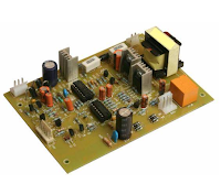
One of my customer brought this Inverter for repair saying that over load indication and no output from the outlet.
 |
| One came for repair |
Once you became an expert in repair this above model you can repair almost 50 models having different chassis design in a single PCB package available in market.Some will be having inbuilt smps charger and some will be having external step down transformer charger design. Pls click below link for your understanding to check the different models available in local market.
 | ||||||||||
| external charger Cfl Inv PCB |
This is the one sample pcb uses an external Charger using step down transformer.

This is the one Using internal SMPS Charger design.They employed in compact design.
Anyhow let's come back to my repair story How i repaired one came to repair.Before going to repair one should know what is inverter? How it works? What is the function of comparitor in inverter/UPS? PWM ic etc.
I think these kind of terms are studied in your Technical courses in ITI/Diploma/Engg.Again i am recalling these terms here & i will let you know how they housed to form this beautiful power house equipment home inverter.
Generally i think you know inverter comes with different options like
1)Over charger protection
2)Over load protection
3)Inv Mode(Battery Backup mode
4)Mains mode
Don't worry about this controllers its quite common all in the ups/inverter design.
The main Heart of the circuit is SG3524,I have seen this IC from past 20 years.I studied this data sheet before coming to UPS field long back & no Internet during that time.
Common Section are.
1) PWM Generator(SG3524)
2) Comperator (LM339)
3)Buffer section
4)Main output section (Using mosfets &HF Transformer)
I cannot explain all this terms now . I am dealing what was the fault i noticed which came to repair in my work bench.Let us start.
When I switched ON the equipment in battery mode , Inverter is getting Over load and is Indicating same.As further investigated and started to debug. pls go through the below diagrams for your understanding. In Over load condition IC SG3524 is getting 5Volts
instead of zero at shutdown pin 10.
Further investigated the reason to cause this fault. checked the mosfet found ok,Checked the battery voltage sensing circuit found ok,For your information all these sensing are configured via ICLM339,So replaced the IC LM339 but fault not cleared.Now its really hard time to investigate the fault cause. Checked all the possibility found ok but mainly need to know the reason to cause fault at shutdown pin.

Usually based on my repair experience on repairing such faults i commonly notice Mosfet shorts,Fusible resistance carrying 12volts battery voltages open and drysolder in current stress area.Because i solved many number of Inverts in my carrier.
But i came across all this testing and found ok in my bench even i could not able to solve this fault.
SG3524 INTERNAL STRUCTURE

Typical inverter block diagram

Ultimately i suspected on HF Transformer could be leaky.Usually we cannot identify or test the transformer leaky complent and even over load sensing current DC which is happening in fraction of seconds.
I disordered the Transformer and pulled my Blue ring tester and checked the condition.Finally got the culprit ,yes transformer has gone bad my ring tester LEDs blinked off.
Opened my junk replaced the transformer.On power on in battery mode equipment worked perfectly with mains change over .Customer felt very happy this is one of my success story.
Regards
Basavaraj:BM