By Basavaraj BM
Electronics Debug Engineer | Repair Blogger
📦 Product Overview – boAt Avanto Bar Mavan Model
✅ Key Specifications:
| Feature | Details |
|---|---|
| Model | Avanto Bar Mavan |
| Power Supply | 24V DC (external adapter) |
| Audio Output | 2.1 Channel (stereo + subwoofer) |
| Output Power | ~40W RMS total |
| Display Type | LED Digital Display |
| Input Options | AUX / USB / SD / FM / Bluetooth |
| Remote Control | Yes |
| Main Board Voltage | 5V DC (via buck converter) |
| DC-DC Converter IC | Originally XL1509-5.0 |
| Speaker Configuration | 2 Speakers + 1 Subwoofer |

boAt Avanto Bar Mavan Model
⚠️ Problem Diagnosis – No Power, Dead System
My first inspection showed that the unit was completely lifeless. After tracing the power supply path, I found the culprit:

🔥 The DC-DC converter IC (XL1509-5.0) was burned out.
This IC is crucial for converting higher input voltage to a regulated 5V output required for the board’s logic and control circuits.
🔬 Challenge – Extremely Compact PCB Design
The PCB in this model is very compact and tightly packed, making it very difficult to probe or analyze faults using conventional debugging tools.
Due to the minute layout and inaccessible tracks, I initially made up my mind to replace the entire board with a new TPA3116-based 2.1 Bluetooth Class D amplifier module.
Replacement Consideration:

-
Module: TPA3116 2.1 Bluetooth Class D Power Amplifier Board
-
Output Power: 50W x 2 + 100W Subwoofer
-
Estimated Cost: ₹6,150
Though this would have been a modern upgrade with higher output, the cost was too high for the customer, and they did not approve the modification.
❌ Online Order Misfire – Wrong IC Received
I had ordered the original XL1509-5.0 online, but unfortunately, the wrong version (3.3V) was delivered—which was unusable for this circuit.
🧠 Smart Work – Local Sourcing and an Alternative Plan
Instead of wasting more time and money, I decided to go with a simple, cost-effective alternative that could still get the job done.

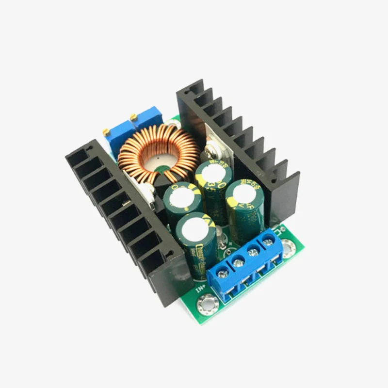
At a local shop, I picked up a XL7015 adjustable buck converter module. This module is easily available, reliable, and perfect for generating 5V output with fine tuning.
🔧 Fine-Tuning the Fix – 5V Precision Setup
-
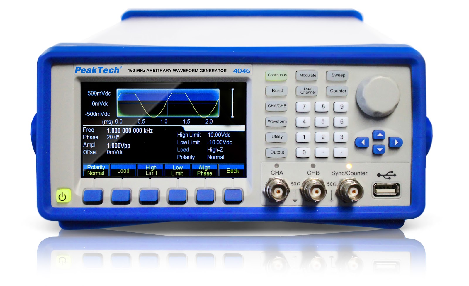
Connected the XL7015 module to my bench power supply.
-
Adjusted the onboard potentiometer using a multimeter to set the output to exactly 5.00V.
-
To ensure long-term stability, I glued the potentiometer after adjustment to avoid voltage drift.
-
Installed the module in place of the burnt IC and routed the output line carefully to feed the 5V rail.
✅ Success! System Revived and Fully Functional
After everything was wired and checked, I powered on the system—and to my satisfaction, the Avanto Bar Mavan was fully revived:
-
Power LED turned on
-
Display functioned normally
-
Music output through all speakers was crystal clear
🎉 Another successful and budget-friendly repair!
💡 Key Learnings from This Repair
-
Compact PCBs are difficult to repair, so sometimes replacing the entire module is tempting—but not always affordable.
-
Always cross-check IC part numbers while ordering online.
-
Local sourcing can save time and provide quick solutions.
-
The XL7015 module is a fantastic alternative to fixed-output regulators when adjusted precisely.
-
Securing the potentiometer after adjustment is critical to maintain stable output voltage.
If you're facing similar challenges, consider practical alternatives instead of costly module replacements. Good diagnostics and clever solutions can save both time and money—while keeping your customers happy!