Hi Dear friends,
Welcome back again to Electronic Repair Article.
In the modern audio system Blue tooth is playing very important role. This is
because it’s very flexible to the User which eliminates completely plug and
play audio jack system from your android smart phone to relevant audio player.
This blue tooth system is now very popular in all most all the
modern audio systems from cheaper end to higher end audio player devices,
In those days our generation people had the
life like one Tape cassettes memory only 10 audio songs
followed by CD'S,DVD'S, blue ray disks
and USB by gradually increased their
respective memory space size depending one's their choice.
Now blue tooth Audio players occupied their places. With the
introduction of the Internet, smart phones and android apps peoples are
attracted much more on blue tooth devices because this is also eliminating
storage and maintains. Peoples directly extract the data or audio files from
the web.
Some of the peoples throwing their old professional audio
equipment's to dustbin and busy in purchasing Modern blue tooth audio devises.
As we know PA audio systems are very high cost and we don't
have a mind to throw dustbin because of blue tooth non availability.
Below my story is the solution for the above problem let me
begin my story,
One of my costumers brought a PA audio mixer for repair which
is completely dead. He said if repair cost more not to repair and he is in the
mood of purchasing new mixer with blue tooth technology.
As per his instruction started to debug and there was a
problem in the input power section resulted step down transformer primary open
replaced the same and made it up and re-gained life.
Even though the costumer was not happy because he was
completely attracted to modern blue tooth based mixer. He was in the mood of
throwing to dustbin. When i played this repaired mixer with audio jack
played excellent very high quality sound questioning myself such beautiful
equipment and higher end audio mixer why he is throwing dustbin? Is there any
solution to convert this into blue tooth? The answer is yes.
Here is the chip. Hats off to the inventor. Using this below
chip one can convert any audio system into blue tooth starting from lower
end to heigher end audio system.
Below is the list you can convert to blue tooth with similar
steps
1) Old home theatre audio systems
2) Proffecionsl audio mixer
3) Any audio amplifiers
4) Very old cassette /CD/DVD Audio players
5) Public address audio systems
6) Power amplifiers
7) CRT/LED/LCD tvs etc
8) Automobile audio systems and sub amp systems
.
As continue repair story after replacing defective step down main
transformer and tested the audio output with aux input jack connection via my
smart phone resulted excellent sound output when i hooked to my power amplifier
.My next task is conversion it in to wireless blue tooth technology.
Blue tooth module :-
 |
| BLUE TOOTH CHIP |
Below is the steps i have taken for the conversion and
resulted success.
1) Finding the controlled audio input path for both
left and right channel
Below is the points in finding controlled audio input path in
any amplifier and is very easy as a clue
a) middle pin of the volume controller( Old classical method)
b) Audio amplifier ic data sheet in an internet or data sheet
book
c) Aux input paths (Usually almost all the amplifier will have
aux input/output points)
How i have done:-
Hear for the conversion what i have selected is
audio mixer which is messed with number of volume controllers leads to
confusion .
A professional audio service engineer will easily
finds the connection points but for the new comers its quite confusion. We need
to go in a systematic way.
Please note the below point what i have done to find the audio
input points. Just i played the audio track with the usb and tracked the
AUDIO signal flow using my oscilloscope probe.
 |
| Audio signal flow tracking using Oscilla scope |
Now, raised and lowered input level using mixer channel
volume control to check the out put level. Audio amplitude waves
varied in my oscilloscope accordingly; ultimately i got the Controlled
audio input point as shown below.
 |
| Audio input points both left and right channel |
Above points are
identified and found controlled audio input points RIGHT, Gnd and LEFT Channel
Which is wired via
core cable?
2)
Finding the ripple free pure 5volt/500ma and chassis ground path.
For the blue tooth chip operation fine ripple free
5v/500ma Regulated power supply is required.
Generally we
know professional audio equipment will operate more than 12volts depending
upon their wattage. Here in my case (Audio mixer) it is operating 12 volts DC .We
can use this voltage to convert 5volts using 7805 Regulator.
 |
| Identified 5Volts DC in the mixer |
Since this mixer is
hooked with module USB Audio and FM Radio player which is operating on
5volts already present. Identified the 5volts point and soldered as shown.
 |
| Bluetooth chip installed |
All the points are soldered and now the time is ready for
the testing, I have taken my Samsung smart phone and turned on the blue
tooth in Mixer ON condition. Got th BT3.0 Symbol and paired.
Played my mp3/mp4 files excellent output. Checked the distance
wireless about 15 meters got the power output without any disturbance. Happy to
see this and share my success story in this blog.
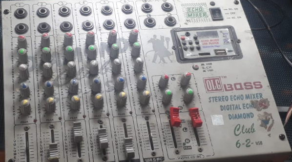
Audio 6 channel mixer undergone for Bluetooth conversion
Dear repair friends
please don't allow your customers to throw their old audio equipment's to dust bin.
Convert them into latest blue tooth audio player as i did to above audio mixer.
You can convert any audio equipment into blue tooth as stated in the list
above. Hope you enjoyed my blue tooth conversion story meet you in the
Next session take care.
Best regards
Basavaraj BM


