Tuesday, 8 July 2025

Sony STK-402-102 Amplifier Using TPA3116D2 Audio Board – A Smart Upgrade Journey

 Reviving a Sony STK-402-102 Amplifier Using TPA3116D2 Audio Board – A Smart Upgrade Journey

By Basavaraj B M – Electronics Debug Engineer with 20+ Years of Experience


🔧 Introduction

The Sony STK-402-102 is a well-known hybrid audio amplifier IC, loved for its warm analog sound and strong output—ideal for Hi-Fi music systems. But when these modules fail, repairs can be difficult and expensive due to discontinued ICs or fake replacements.

In this article, I’ll walk you through how I successfully brought a dead STK-402-102-based amplifier back to life by smartly replacing it with a TPA3116D2 Class-D amplifier board, achieving impressive results at a fraction of the cost!


⚡ Original Issue

The original amplifier stopped working—no output, and the heatsink was warm even in idle. Here’s what I found during diagnosis:

  • No speaker output

  • STK-402-102 IC heating up abnormally

  • ±35V supply was intact

  • Speaker protection relay not clicking

  • Confirmed STK-402-102 was dead

Instead of chasing a replacement STK (many fake ICs flood the market), I decided to modernize the amp using the reliable TPA3116D2 stereo amplifier board.


🔁 Why TPA3116D2?

The TPA3116D2 is a Class-D 2x50W amplifier IC from Texas Instruments. It’s:

  • Compact

  • Energy efficient

  • Easily available

  • Operates at 12V–24V DC

  • Has excellent sound clarity and low distortion

This makes it perfect for retrofitting old analog amplifier cabinets where original parts are no longer available.


🔩 Step-by-Step: Re-Lifing the Amp

1. Remove the STK-402-102

  • Desolder the original STK IC carefully.

  • Remove the heatsink (you may reuse it if needed for the TPA board).

2. Prepare Power Supply

  • The STK used ±35V, but TPA3116D2 requires DC 12V–24V only.

  • I added a DC-DC buck converter module (XL4016) to step down ±35V to 24V DC.

💡 Tip: Use only the positive rail (e.g., +35V to GND) and step it down to 24V DC.

3. Mount the TPA3116D2 Board

  • Secure it inside the same amplifier chassis.

  • Ensure proper insulation and airflow.

  • Attach a small heatsink with thermal paste.

4. Wiring the Inputs and Outputs

  • Connect the RCA input wires to the TPA input pins.

  • Route the speaker wires to the TPA output screw terminals.

  • Ground everything properly to avoid hum or noise.

5. Volume Control

  • Some TPA boards come with a volume potentiometer.

  • If not, reuse the existing volume knob (match the pot resistance).

6. Power ON Test

  • Connect 24V to the TPA board (from the DC converter).

  • Test with small speakers first.

  • Gradually test higher volumes.


🔊 Result and Audio Quality

After powering on, I was surprised with the clean, punchy audio output. The bass was tight, and the treble was crisp. I tested various speakers, including 8-ohm Hi-Fi woofers, and it performed flawlessly even at 70–80% volume.

The amp is now more efficient, lightweight, and cool-running—unlike the old STK which ran hot even at idle.


✅ Pros of This Upgrade

  • No more STK IC worries or overheating

  • Efficient Class-D technology

  • Compact board fits perfectly

  • Budget-friendly repair

  • Excellent sound for daily use


⚠️ Caution and Tips

  • Always test with proper fuse protection

  • Avoid direct connection of ±35V without conversion

  • Use a good filtered SMPS or regulated DC supply

  • Isolate the metal chassis if needed to avoid ground loops


🧰 Tools & Parts Used

  • TPA3116D2 Amplifier Board (2x50W or mono 100W)

  • XL4016 DC-DC Buck Converter

  • Multimeter, Soldering station

  • Capacitors and wires

  • Insulating spacers and thermal paste


🎯 Conclusion

By swapping the old analog STK-402-102 module with a modern TPA3116D2 board, I gave a dead Sony amplifier a second life—with more power efficiency, reliability, and surprisingly good sound.

If you’re a technician or hobbyist with an old STK-based amp on your workbench, this is a perfect DIY upgrade worth trying!


Have you done a similar upgrade? Or facing issues with STK amplifiers? Share your story or ask questions in the comments below!


🔋 XL4016 DC-DC Buck Converter – Overview for Audio Projects

The XL4016 is a high-power step-down (buck) DC-DC converter that is ideal for converting higher DC voltages (like +35V) down to safer, lower voltages (like 24V or 12V) — perfect when repurposing old amplifier power supplies to modern Class-D amplifier boards like TPA3116D2.


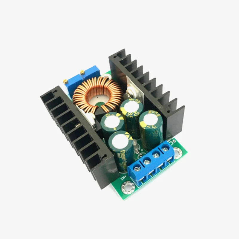
📦 Key Features of XL4016

ParameterValue
Input Voltage8V to 40V DC
Output Voltage1.25V to 36V DC (adjustable)
Output CurrentUp to 8A (with heatsink)
EfficiencyUp to 95%
Switching Frequency180 kHz
Output RippleLow, with proper filtering
Cooling Required?Yes, heatsink or fan for >5A

⚙️ How It Works in Audio Amp Conversion

When replacing a ±35V analog audio IC like STK402-102 with a TPA3116D2 board, the high voltage must be stepped down. Since TPA3116D2 runs best at 12V–24V, the XL4016 is used as:

Example Setup:

  • Original PSU: ±35V from center-tapped transformer

  • Tap only the +35V to GND

  • Feed this to XL4016 input

  • Adjust XL4016 output to 24V DC

  • Connect this to TPA3116D2 amplifier board


🪛 How to Use the XL4016 in Your Project

  1. Connect Input:

    • VIN+ to +35V

    • VIN– to GND

  2. Adjust Output Voltage:

    • Turn potentiometer while measuring with multimeter

    • Set it to 24V (or 21V for safety)

  3. Connect Output:

    • VOUT+ to the TPA3116D2 power input

    • VOUT– to GND

  4. Heatsink/Fan:

    • If drawing more than 3–4A, use heatsink or cooling fan

  5. Protection:

    • Add a fuse on the input side (e.g., 3A)

    • Ensure good ventilation in the cabinet


⚠️ Precautions

  • Do NOT reverse polarity — it can damage the module

  • Do NOT exceed input voltage (max 40V)

  • Use electrolytic capacitors at input/output to suppress ripple

  • Avoid loading above 6A continuously without extra cooling


Why It’s Perfect for Audio Retrofitting

  • Cheap and easy to find online

  • Compact and fits in most old amplifier cabinets

  • Lets you reuse old transformer-based supplies

  • Smooth output with minimal noise (important for audio)


Regards

Basavaraj BM

How a Signal Generator Helps in PCB Repair

 Great question! A signal generator (also known as a function generator) is another very useful tool for electronics repair and testing. While a digital oscilloscope helps you see signals, a signal generator helps you inject known signals into the circuit. This makes fault-finding and performance testing much easier—especially in analog audio, RF, communication, and digital circuits.


🛠️ How a Signal Generator Helps in PCB Repair

🔹 1. Testing Amplifiers and Audio Circuits

When repairing audio amplifiers or speaker systems:

  • You can inject a 1kHz sine wave into the amplifier input.

  • Observe the output on the oscilloscope.

  • A clean sine output means the amp is working fine; distortion, clipping, or no signal means there’s a problem.

✅ Real Use: I once repaired a PA amplifier by injecting a test tone. The preamp stage was fine, but the power stage wasn’t amplifying. Tracing the signal stage by stage helped isolate the faulty transistor.


🔹 2. Troubleshooting Stages in Signal Path

In communication or processing circuits, you can:

  • Inject square waves or pulse trains.

  • Check how each section processes the signal.

This is useful in:

  • Filter circuits – To test frequency response.

  • Digital logic ICs – To simulate clock or data inputs.

  • Timing circuits (e.g., 555, counters) – To trigger or reset circuits.


🔹 3. Testing Oscilloscope and Probes

You can also use the signal generator:

  • To calibrate or verify that your oscilloscope probe is working correctly.

  • To test bandwidth and distortion measurement setups.


🔹 4. Simulating Missing Signals

In faulty boards, sometimes the microcontroller, clock circuit, or sensor isn't producing signals. A signal generator can simulate those inputs to test whether the next stage works.

✅ Real Use: In one project, a dead IR receiver circuit wasn’t triggering the output stage. I injected a 38kHz modulated signal using the generator and confirmed that the output section worked. So the IR sensor was faulty.


🔹 5. Component Testing

Some passive components (filters, transformers) and even certain ICs can be tested by applying known signals:

  • Use sweep function to test filters.

  • Inject low-frequency signals to check transformer or coupling capacitor behavior.


📊 Summary Table: Where Signal Generator Helps

ApplicationSignal UsedPurpose
Audio amplifier testingSine wave (1kHz)Check output stages
Digital logicSquare waveSimulate clocks/data
IR/remote circuit38kHz modulatedTest receiver function
Filters/RC circuitsFrequency sweepAnalyze response
Faulty microcontrollerPulseSimulate missing trigger
Signal tracingAny waveformTrack signal path with scope

🔧 Final Words

A signal generator + oscilloscope is a powerful combo. You inject a test signal using the generator and observe the circuit's response using the scope. Together, they help:

  • Reduce guesswork

  • Find open signal paths

  • Verify functionality stage-by-stage

  • Speed up complex repairs

Whether you are working on LED TVs, amplifiers, SMPS, or embedded boards, the signal generator is a must-have tool for serious electronics repair.


Absolutely! A signal generator is very helpful in troubleshooting SMPS (Switched-Mode Power Supply), especially during fault-finding and when the control IC is not producing signals, or when you're checking gate drive, transformer behavior, or startup problems.

Here’s a clear breakdown of how a signal generator helps in SMPS repair:


⚡ How Signal Generator Helps in SMPS Troubleshooting

🔹 1. Simulate PWM Gate Signals

Many SMPS circuits use a PWM IC (like UC3842, TL494, SG3525, etc.) to drive MOSFET gates. If the IC is dead or not producing output, you can:

  • Inject a PWM signal (e.g., 20kHz–100kHz, 5V peak) from the signal generator into the gate of the MOSFET (through a gate resistor).

  • Observe whether the transformer starts switching and output voltage appears.

Real Example: I had a dead SMPS where the PWM IC was faulty. Injecting a 50kHz square wave to the gate proved the power stage was fine. Only the control circuit needed repair.


🔹 2. Testing Transformer Behavior

Injecting a square wave into one winding of a transformer allows you to:

  • Check for proper inductive behavior (waveform on secondary).

  • Identify shorted turns or open windings.

  • Observe waveform ringing or distortion if the transformer is damaged.

Use low voltage (1–5V) and limited current to avoid damage.


🔹 3. Triggering Protection Circuit Debugging

Some SMPS have over-voltage, over-current, or feedback protection. If the SMPS shuts down instantly, you can:

  • Inject a test signal into the feedback or sense line.

  • Confirm whether the protection is falsely triggering.

Example: One supply had a feedback pin stuck high. Injecting a 2V DC + ripple waveform showed that the supply would restart only when FB was normal. Fault traced to an open opto-coupler.


🔹 4. Clock Injection in Synchronous Designs

Some SMPS designs (especially digital ones) use external clock sources. If the clock crystal or oscillator fails:

  • You can inject a square wave clock signal into the IC’s clock input.

  • If SMPS starts working, it confirms clock section is faulty.


🔹 5. Output Ripple Simulation for Post-Regulator Testing

If the output of SMPS feeds another regulator (e.g., LDO), you can:

  • Inject a signal with ripples or noise to the input.

  • Observe how the next stage handles it (ripple rejection, filtering, etc.)


🧪 Caution When Using Signal Generator on SMPS

Do'sDon'ts
Use low-voltage signals (5V max) when injecting into gates or transformerDon’t inject high voltage directly—can damage components
Always isolate ground between signal generator and live SMPSNever connect signal generator ground to high-voltage circuits directly
Use series resistors (1k–10k) to limit currentAvoid driving directly without limiting circuit

✅ Summary Table

PurposeSignal TypeUse
Test gate drive20–100kHz square waveSee if MOSFET and transformer respond
Test transformer1kHz–10kHz square waveCheck for waveform on secondary
Debug feedbackRamp, DC + rippleSimulate normal feedback signal
Replace missing clockSquare wave (fixed freq)Restart controller temporarily
Verify filteringNoisy sine or burstTest post-regulator behavior

🛠 Real World Tip

When debugging a dead SMPS, combine:

  • Signal Generator to inject known signal into gate or feedback,

  • Oscilloscope to monitor output and switching behavior.

This speeds up repair and avoids blind trial-and-error.

Regards
Basavaraj BM

The Role of Digital Oscilloscope in Troubleshooting Electronic PCBs


In the fast-paced world of electronics repair and diagnostics, the digital oscilloscope stands out as one of the most powerful and versatile tools for troubleshooting Printed Circuit Boards (PCBs). Whether you are working on power amplifiers, SMPS, LED TVs, or microcontroller-based circuits, a digital oscilloscope can reveal the “invisible” world of signals and help you identify the root cause of failures with precision and confidence.

Why Oscilloscopes Matter in Electronics Repair

A multimeter can only show voltage, current, and resistance. But electronic circuits operate in dynamic conditions—waveforms, frequencies, pulses, and switching signals. That’s where a digital oscilloscope comes in. It allows you to visualize signal behavior in real-time, helping you catch issues that static tools cannot detect.

Key Roles of a Digital Oscilloscope in Troubleshooting

1. Waveform Analysis

A digital oscilloscope captures and displays voltage vs. time, allowing you to observe:

  • Shape of signals (sine, square, triangle, etc.)

  • Frequency and period

  • Noise, distortion, or unexpected spikes
    These details are essential in diagnosing analog stages in amplifiers, audio equipment, and signal processing circuits.

2. Clock and Data Signal Verification

In digital circuits, checking logic levels is not enough. You need to verify pulse width, timing, rise/fall time, and duty cycle. A scope helps in:

  • Debugging microcontroller clock issues

  • Checking serial communication (UART, I2C, SPI)

  • Ensuring proper timing between digital devices

3. Power Supply Ripple and Noise Diagnosis

A power supply may show 5V on a multimeter, but have hidden high-frequency noise or ripple. Oscilloscopes reveal:

  • Output stability

  • Ripple voltage in SMPS or linear regulators

  • Spikes caused by faulty capacitors or layout issues

4. Component Behavior Observation

With a scope, you can see how components behave under load:

  • Gate signals of MOSFETs in SMPS

  • Switching of transistors in amplifiers

  • PWM duty cycles in motor controllers or LED drivers

5. Short Circuit and Open Line Detection

When no signal appears at a test point, it may indicate:

  • Track cut/open trace

  • Bad solder joints

  • Shorted components pulling the signal down
    Scopes help you follow the signal path to isolate the problem area.


Real-Life Example:

Recently, I repaired an LED TV with intermittent backlight issues. The power board’s PWM controller seemed fine on a multimeter. But the oscilloscope showed that the gate pulse to the MOSFET was irregular. The root cause? A dried-out capacitor affecting the PWM frequency. Without a scope, it would’ve taken much longer to trace.


Choosing the Right Oscilloscope

For general electronics repair:

  • Bandwidth: 50–100 MHz is enough

  • Channels: 2–4 channels

  • Storage: Deep memory helps capture long signals

  • Triggering Options: Helps isolate faults like glitches or delayed pulses

Brands like Rigol, Siglent, Owon, and entry-level Tektronix offer reliable options for repair engineers.


Conclusion

A digital oscilloscope is more than just a fancy screen—it’s your window into the electrical soul of the PCB. It reduces guesswork, saves time, and brings clarity when multimeters and logic probes fall short. Whether you’re a hobbyist, technician, or professional engineer, mastering the oscilloscope is a crucial step toward expert-level troubleshooting.


Here’s an expanded real-life example section showing how digital oscilloscopes helped in actual repair cases. You can use these in your blog or YouTube video scripts:


🔧 Real-Life Examples: How Oscilloscopes Helped Me Solve Tough PCB Problems

1. SMPS Dead – Hidden Low ESR Problem Found

A 12V SMPS was completely dead. Input fuse and primary FET were good. The PWM IC (UC3842) was getting Vcc, but there was no gate pulse.
Using the oscilloscope, I probed the feedback and Vcc pins. The scope showed that the Vcc was pulsing rapidly and resetting—a clear sign of bad capacitor ESR.
👉 Replaced the capacitor near the Vcc pin, and the gate pulses resumed immediately. SMPS came back to life.

2. LED TV – No Display But Backlight ON

Customer complained of "no picture, only sound" on a 32" LED TV. Backlight and voltage rails were present.
Using the oscilloscope, I probed the LVDS output lines from the main board. One or two LVDS lanes were dead flat—no data pulses.
👉 The problem was traced to a faulty BGA chip or dry solder. Reflowing the chip fixed the issue.
Without the scope, I would have guessed T-CON or panel.

3. Ahuja Amplifier – Output Distortion

A 120W PA amplifier was showing humming and distorted output even with a clean input signal. Multimeter showed all voltages were okay.
I connected the oscilloscope to the speaker output and saw a 50Hz ripple riding on the audio waveform. Then I checked the DC rails—there was excessive ripple.
👉 Filter capacitor was weak despite reading full voltage on DMM. After replacing the cap, audio became clean and powerful.

4. Microcontroller-Based Timer – Irregular Output

In an industrial timer board based on an AT89C51 MCU, the relay would not switch reliably.
Probing with a multimeter showed +5V everywhere. But the oscilloscope revealed that the clock crystal was not oscillating properly—signal was unstable.
👉 Replacing the crystal and loading caps solved the issue.


🔍 Summary: Why These Cases Needed a Scope

ProblemMultimeter ShowsOscilloscope RevealedFinal Fix
SMPS deadVcc OKPulsing/reset VccReplaced bad cap
LED TV no displayRails OKMissing LVDS pulsesReflowed main chip
Amp distortionAll voltages OKRipple on DC lineReplaced filter cap
Timer unstable5V OKClock not stableReplaced crystal

Regards
Basavaraj BM

Do You Really Need a Voltage Stabilizer for SMPS?


Author: Basavaraj B M
Electronics Debug Engineer | 20+ Years Experience | SMPS, PA Amplifiers, and More


Introduction

Many technicians and consumers ask:

“Should I use a voltage stabilizer with a device that already has SMPS?”

This blog clears the confusion around whether SMPS-based equipment like LED TVs, audio amplifiers, routers, or even desktop PCs really need an external voltage stabilizer—and when it's useful, harmful, or unnecessary.


What is an SMPS?

An SMPS (Switched Mode Power Supply) converts incoming AC voltage to DC using high-frequency switching. Key benefits include:

  • Wide input voltage tolerance (often 90V–270V AC)

  • Compact and efficient

  • In-built protection (overvoltage, undervoltage, short circuit)

Modern electronics (LED TVs, set-top boxes, monitors) already use SMPS, making them more resistant to voltage fluctuations compared to older linear transformer designs.


🔌 What is a Voltage Stabilizer?

A voltage stabilizer is designed to:

  • Correct high/low voltages

  • Protect devices from brownouts and spikes

  • Deliver steady voltage to the connected load

They were essential when devices used sensitive transformer-based power supplies (e.g., CRT TVs, tape decks).


When You Don't Need a Stabilizer for SMPS

If your device has:

  • A wide input voltage SMPS (90–270V AC)

  • Is rated for Indian grid fluctuation range

  • Has inbuilt surge protection or MOVs

Then an external stabilizer is redundant.

Example:

  • LED TVs, modern PA amplifiers, desktop SMPS: work directly from 170–270V AC.

  • Many modern LED TVs mention “No Stabilizer Needed” on the back panel.


⚠️ When a Stabilizer May Be Useful

You may still consider a stabilizer when:

  • You face frequent power cuts, low voltage (<160V), or high voltage (>280V)

  • You are using expensive audio equipment, sensitive lab instruments, or old SMPS designs

  • Your local supply is unpredictable or noisy

In such cases, a modern digital stabilizer with surge suppression and cut-off feature can protect the input stage of the SMPS.


When a Stabilizer Can Cause Problems

Some stabilizers:

  • React slowly to voltage changes, causing relay click noise

  • Add unnecessary load or heat

  • Create harmonics or waveform distortion (if poorly designed)

Also, connecting a low-cost stabilizer to an SMPS can result in over-regulation or conflicts with inrush current, especially in audio amplifiers or LED TVs.


🔧 Real-Life Case: PA System Repair

A client was using an Ahuja 120W amplifier with a local stabilizer.
Issue: Humming sound and relay clicking.
Diagnosis: The stabilizer’s relay was delaying the AC phase, confusing the internal SMPS and relay of the amplifier.

Solution: Removed the stabilizer. Direct connection improved performance.
Conclusion: Stabilizer was causing more harm than good.


🧠 Conclusion

SMPS is already a “mini stabilizer” inside your device.

So:

  • For modern equipment in moderate grid conditions, stabilizer = not needed.

  • In rural or extreme grid areas, use a good-quality digital stabilizer with overvoltage and surge protection.

  • Avoid using cheap or old relay-type stabilizers with SMPS loads.


🔍 Quick Checklist

Device TypeSMPS Inside?Stabilizer Needed?
LED TV (2020+)Yes❌ Not required
Desktop PCYes❌ Unless power is bad
Ahuja AmplifierYes (partial)⚠️ Only if unstable grid
CCTV DVRYes❌ Usually not required
Washing MachineNo/Partial✅ Use stabilizer

💬 Final Note

If you’re unsure whether your setup needs a stabilizer, feel free to comment below or message me. I'm always ready to help fellow technicians and electronics users with practical, tested advice.


Regards

Basavaraj BM